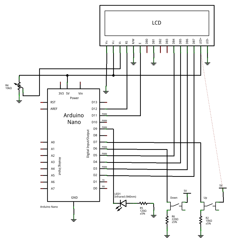
Today I’d hoped to go out and create a time lapse video with my intervalometer, but this being Scotland it’s raining and the sky is a uniform grey. So a good opportunity to go over the intervalometer design.
The circuit is very simple, most of the details can be cobbled together using the examples on the Arduino website. So this morning I’ve been playing with an Open Source drafting tool to draw a circuit diagram. Fritzing is provided by the Interaction Design Lab of the University of Applied Sciences Potsdam. I just set about drawing my circuit and learning Fritzing along the way. The result is not pretty, but it will do. That is no fault of Fritzing! For my next project I’ll spend some time learning how to use it properly.
Now this is far from perfect, but that’s what happens when you don’t RTFM. To get the circuit diagram into the post I used GIMP for the first time, the open source graphics tool. The UI is very unfamiliar, but I managed to crop the export from Fritzing. When it comes to processing the images from the camera I’ll need to get a lot more familiar with GIMP. It looks very different to Photoshop!
For this project I source my components from Ebay. A bag of 5 IR LEDS for about £1.00, the 16×2 LCD panel for £2.95, two panel momentary pushbuttons for £2.95, a bag of 5 trimmer potentiometers for about £1, and a clone Arduino Nano board for £11.00. All prices including postage.
I built the circuit first on a breadboard then, once I had the code working, moved it to a piece of veroboard and mounted the whole lot in a small plastic box I got from Farnell.
Next time I’ll post and explain the code I’m using now and how I got there.
Just spotted a small error in the circuit diagram, R6 should be 10k Ohm the same as the pull down on the other switch.


To think, I was confused a mntiue ago.